Module 6 - Setting up the OS6 Software
Account Management
Roles
There are four different User Roles:
- 'Light User' - Read-only access with limited functionality
- 'User' - Ability to acknowledge/dismiss alerts
- 'Trained User' - As 'User' with addtional privileges such as area editing and area suppression
- Elevated Trained User (Super User) with full access to make changes to Detectors and System Architecural changes
Users will need to provide a unique name and associated password. This password must meet the password complexity requirements.
Add/Modify/Delete users
Accounts on a system can be modified via Account Management Window. New users can be added by clicking the ‘New User’ button. Note: The access that a user has will depend on their own user type. For instance, Light Users will only have the access rights to change their username and password.


The user details can then be populated with their preferences (including language) and assigned the suitable role. Once complete, press OK and the new user will appear in the account management window.
System Lockdown
Critical areas within the system are locked down to prevent changes to the System. Only users with SuperUser Access rights can access these areas and requires a TOTP code in order to login with elevated access.
Super user access will allow full access to make changes to any part of the System. Please note changes to the System could have unexpected issues, resulting in a non-functioning System, requiring Luna Engineers to rectify. If this is Elevated access is required, please discuss with your Luna representative before peforming proceeding
TOTP codes are available from the authorisation server auth.optasense.com, to which access needs to be setup.
A TOTP code is a Time-based One-Time Password. This is a temporary, unique code required for two-factor authentication (and changes every 60 seconds).
Forgotten Password (Superuser)
In the case a user cannot remember their password, the password can be reset. This can be done from the login page by using the ‘Forgot Password’ link. This link requires a OTP code. Superusers can also reset the password of regular users from the Accounts window.
Data Management
Overview
The OS6 Distributed database stores the following items:
- Alerts and their associated updates
- Audits
- Process Metrics
Copies of these items are shared across the PUs in the distributed database for redudancy purposes.
Data Retention Policy
The Data Retention Policy allows configuration of the length of time that various threats, statistics, and logs are retained on the system. These are accessed by expanding the required section using the drop-down arrow on the right-hand side. The user can then input the desired duration, noting that longer durations require additional overhead that can potentially result in System issues (slowdowns etc.)


Rolling Recorders
Rolling Recorders can be configured to store data for an allocated amount of time, based on disk space. The main rolling recorders are the histogram and sensor data. While some algorithms also produce recordable data.
The rolling recorder configuration window will show the available disk(s) associated with the selected node and the disk allocation for each data source. The system will calculate an approximate idea of how much data the current configuration will allow to be captured for each recorder.

It is possible to change storage allocation to each stream by right clicking a stream and adjusting the allocated storage space, shown as a percentage of the available space on the rolling recorder drive.
Alert Filtering Management
Alert Filtering
Alert Filtering allows the configuration of the alert types to be displayed on the current CU. This is unique to each CU that the software is being run on and allows different CUs to be configured for different purposes.

Within Alert Filtering, it is also possible to configure the threat expiry time for each alert type. Select the icon to the right of the high alert icon for each alert to do so. This opens the configure alert expiry time window. From here, times can be altered and set to permanently display the icon on the map interface (until the alert is acknowledged or dismissed).

The operator can also create bespoke alert types by selecting Add Bespoke Type. This enables the detectors to be assigned any threat name desired by the client. The Add Bespoke Type window allows input of a custom threat name. By selecting one of the threat icons, the threat icon selection window opens to allow the selection of the threat icon. Custom images can also be assigned to the alert by selecting Load Custom Image.


OPS Filtering
On a system with multiple OPSs, it is possible to use the OPS Filtering category to disable the OPSs not required on the current CU. These choices are unique to each CU.

Config Management
Config Management allows for import and export of config files and folders within the operator software.
Import Config will provide a dialog import an entire config folder or individual elements of a config.
Export Config allows for the export the entire config folder to a target location on the CU. Individual elements can also be exported using the Individual Config Item Export option.
Detector settings are usually stored in an obfuscated format but these can also be exported to CSV to allow for easy access.
Config files should only be changed by an expert user or after consultation with OptaSense Support. Changes to files may require additional user action to utilise the desired changes and uncontrolled changes may be damaging to the system.
Automated backup of configuration
A backup of the OS6 config is performed every 24 hours on each CU. The location of the backup is: C:\Windows\System32\config\systemprofile\AppData\Local\OptaSense\OLA6\SystemBackups
The last 10 backups are kept
OPS Name Mapping
The user can change the name of the OPS rather than using the default OPS number (0, 1, 2, etc.) to a system-specific name. This is configured within the OPS Name Mapping Tab by manually inputting a custom name for each OPS.

Fibre Route
The OPS Fibre Route panel allows the user to make changes to an existing fibre route. This feature is useful should the physical fibre change geographically or the georeferencing of the fibre needs to be updated.
Several visualisation options are available to aid the user when configuring the fibre route.
- Nodes - Displays the pointst that describe the fibre route.
- Fibre Route – Line route showing the current fibre route
- Channel Coverage
- Calibration Points - Location of georeferencing calibration points.
- OPS Names – Name of OPS covering a given section on the fibre route.
- Other OPSes – Show all OPSes
- Centre On Map Display view on chosen OPS
- Fibre Color – Color of fibre route.
- OPS Drop Down – Select specific OPS
Examples of the more important options applied.
Show Nodes: Green circles mark the fibre route and generally denote a change of direction

Show Channel Coverage: Blue circles denote the channel coverage selected and for a linear section of fibre these circles should just touch. Spaces between the circles is physically not possible and should be investigated. Circles can overlap but this usually indicates that there is a coil of fibre that has not been accounted for.

Show Calibration Points: Yellow crosses – used to refernce the fibre to the ground and contain position and optical distance information

The bottom of the configuration panel contains the tools to modify and update the fibre routes.
- Choose fibre route to edit
- Spatial Resolution - This should align with the spatial sampling provided by the IU.
- Point Tolerance - Determines the window of tolerance around a fibre node that the calibration point should be.
- View Nodes / Cal Points table.
- Import/Export fibre route – Refer to Module 4.
- Copy to Cal Point – Takes a selected node point and creates a calibration point. This is the recommended approach for calibration points. (Note, when using, the user must switch to cal points and configure the additional information required to plot the point).
- Add, delete, move node points.
- Reverse order of fibre route nodes. The start of the route should always be located where the IU is.

The user should regularly save their actions as they make changes the fibre configuration. Should a mistake be made the undo button can be used to return to the last saved state.

Fibre Coverage and Calibration Points
The points are represented by blue circles that have the same diameter as the selected spatial resolution. Geo-referencing is required to ensure that the length and route of the fibre that has been be placed onto the map layer is correct and accounts for loops of fibre that may be buried in splice chambers, etc. These loops can then be 'compressed' into a single channel enabling accurate alert posting to the map screen. The channel coverage circles are linked directly to the calibration points.
Calibration points contain data about the relationship between the fibre lay and the physical route allowing the system to accommodate for the difference in length. Right clicking on the desired calibration point will bring up the 'Edit Calibration Point' box. This is where the fibre point can be set. It is advisable to provide a meaningful name for each calibration to indicate where it represents.
It is recommended to create calibration points directly from an existing fibre node so that their location matches identically. This avoids issues that can arise from the calibration point and fibre nodes being separated.

Custom Routes
Similar to Fibre routes, the system provides configurable routes that can serve different purposes. The different options are all configurable within the Custom Routes menu.
Paths
Paths can be created on the Map screen to highlight features like roads, tracks, rivers and other geographical markers.
Asset Route
Asset route mapping allows the operators to create custom routes that can be used within detectors to address the differences between fibre route and asset routes – for instance, the effect of optical coils. Asset routes make use of a 'Fibre to Asset Mapping' algorithm to enable monitoring of an asset in relation to the monitored fibre. Notable examples where this would prove useful would be road and rail assets.
At present, only the Road Detector utilises Asset Routes
Once an asset route has been created, the Show Fibre to Asset Mapping flag will draw lines showing the mapping of each asset route point to the parent route.

Client Scale
Client scales are used to link the fibre points to a preferred reference scale – most commonly mile/kilometre points along the route. Configuration of the client scale allows alerts to be output with custom information that the client may be more familiar with. The client scale can also be used on the waterfall display to change the x-axis from fibre points to . When using a client scale on the waterfall display the x-axis will always run increase from left-to-right; The fibre points will automatically be flipped if the scale runs in the reverse order to the fibre points. While a Client Scale can span multiple OPS, the waterfall display will only display the section that is relevant to the currently selected OPS.
Adding a New Client Scale
Draw the client scale route and assign the client scale to each point. The system will interpolated between pairs of points along the defined route but note that the route is not aware of the underlying fibre route and so the client scale route should have enough fidelity to follow the route.
If coordinates are available in the appropriate CSV format (Latitude, Longitude, ClientPoint), then these can be imported via the import button. Similarly, a defined client scale can be exported.
The Show Fibre to Asset Mapping flag will draw lines showing the mapping of each client scale point to the parent route point.
When creating a client scale, accurate coordinates must be provided by the client as incorrect points could result in a scale not following the Asset/Fiber Route as intended.
Generating a Client Scale Using Customer Coordinates
In most cases, operators would use the 'Add' button to create a Client Scale, and import customer-generated coordinate positions. However in some cases the resolution/accuracy of these coordinates may to too poor to follow the required Detector Route as intended. In this scenario, the 'Generate’ option can be used to generate a Client Scale that will follow the fibre route coordinates.
To generate a Client Scale using Customer coordinates, press the ‘Generate’ button. This will open a dialogue in which the name, colour and parent Detector Route can be supplied. Ensure that the ‘FromFile’ tab is selected and that the customer CSV file has been selected. The OPS’s this Client Scale should apply to also needs to be selected, and any spurs should be removed from consideration.

When the OK button is pressed, a Client Scale will be created using a combination of customer and interpolated coordinates.
A generated scale should be checked to ensure that it provides the expected mapping.
Licencing
Core License
The licencing screen allows inspection of the current licence(s) details on the system and upload of updated licences. Replacement licences can be uploaded by dragging the licence file into the licence panel.

Interfaces
Luna OS6 offers a range of interfaces, including REST, MQTT and various Camera Interface. These Interfaces will populate within the Wizard as they are added to the system via the System Description Editor (see Module 12 - System Resizing).
The available interface controls will depend on which items are licensed to the particular installation and enabled in the System Descriptor.
Further information on the configuration of individual interfaces can be found in Module 8 - Incorporating Ancillary Equipment and Interfaces.
Setting up OS6 to receive DTS (Charon4) Data
Prerequiites
Prior to setting up OS6 to receive DTS Alerts for use within OS6 Leak Fuser, the Charon4 Software must be configured first
Make sure the Charon4 REST Interface is enabled & running
- This is a Windows Service.
- Configure the Fibre route on Charon4.
- Configure the DTS Alerts in Charon4.
If in doubt, please contact your LIOS expert.
Licence
please make sure OS6 has the 'LiosDTSInterface' licence added

Setting up the OS6 Processing Block
Please note a single OS6 PU is required to receive all DTS Alerts/Data for a single install OS6 will allow multiple Charon4 instances to be connected
- To setup the ‘Processing Block’ in OS6, please run the ‘Install Scheduler’ and select the nominated PU
- Enter the name of the Processing Block & number of Fibres
- Select if DTS Alerts will be part of Leak Fuser

On next screen, please enter the DAS / DTS fibre mapping
- This will be used for Leak fusing

Reviewing the Processing Block
Once completed, it is possible to review the DAS to DTS mapping
There is (currently) no way to edit/modify this mapping. If this is needed to be done, please remove this DTS Processing Block and start again
Configuring the DTS Connection
To configure the Charon4 configuration, type the key word ‘Charon4’ into OS6 Map.

- The Charon4 Address is the PC where Charon4 is being run
- Database Name can be found on Charon4 Property Panel
- Username/password is the Charon4 REST username/password
- Charon Project Name can be found on the Charon4 Property Panel
- LIOS Controller details can be found on the Charon4 Tree View


Configuring the DTS Fibre Route
The DTS Fibre routes are setup in the same was as DAS fibres
Please make sure the DTS Fibre route is the same as described in Charon4
Configuring the Rolling Recorder
The DTS Data will have an associated OS6 Rolling Recorder. This can be configured, as per other Rolling Recorders
Configuring the Leak Fuser
if DTS Alerts are being used as part of the OS6 Leak Fuser the following items are required
- The Leak fuser has default DTS Alert weightings set
- If required to change/review the values, select the Leak Fuser Detector Control Panel

Please note, that if a DTS Alert & DTGS Alert is created within the specified Association Period & Distance Threshold, only the Alert with this highest ‘weighting’ will be considered.
System Health
Confirm OS6 is connected and receiving data (DTS & Waterfall) data from Charon4 via System Health

Advanced Setup items
Custom Hardware Monitor
This tab allows the user to Monitor hardware with an IP address on the network. The system will constantly ping the associated IP of the hardware. These can be ECPSs, Managed Switches, etc. By adding these custom hardware items here, they will appear on the system health.
Monitors are added or removed by selecting one of the two icons on the tab. When a new monitor is added or edited, an additional window allows name and IP address input.


Enabling/Disabling licenced Detectors
Checkboxes are provided to enable/disable detectors for each OPS and to enable/disable the publishing of pre-alerts for relevant detectors. The status of detectors for each OPS can be viewed within the Detector Status tab, as shown in the OPS drop-down list.

Additional Detectors
Additional detectors can be viewed and added to the system through the Additional Detectors tab. By selecting Add Additional Detector, an additional window will appear where details for the detector can be specified. Detectors must be based on an existing OS6 detection algorithm. The purpose of adding this is to duplicate detectors for different purposes. For instance, in some systems, it may be necessary to run two instances of the NPP detector to allow detection at different speeds.


FFT Size Configuration
The system will set the FFT size according to the data sampling rate by default. However, it is possible to override the system and specify an FFT size for each OPS.
Please speak to your Luna representative prior to changing the default FFT size, as this may have a negative impact on the system and will affect any algorithms that make use of the system FFT process, so caution should be applied when changing this setting.
Zoom Areas
Zoom Areas provide the ability to magnify user specified areas on the map and display them on the screen at a larger size than their geographical coverage would normally require. This allows, smaller locations that are part of a large system to be visible to the operator without having to zoom tightly in on the area, or by artificially enlarging the feature. This means that alert locations (latitude and longitude) will be correct, where previously with an artificially large area they would not have been correct
Creating a Zoom Area
To create a Zoom Area select the Zoom Area icon from the side bar on the right side of the map window

Click the Add Zoom Area button and the click and drag on the map in order to create an area around a section of the fibre route to be magnified. Ensure that only the area to be magnified is included.
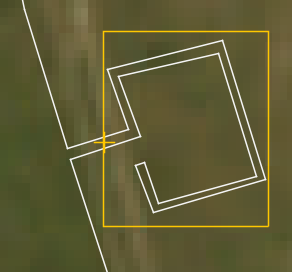
Next, right-click on a location within the newly created area and select Set Zoom Area Origin. Everything within the area will be magnified away from this point.

For example on a block valve station, this should be at the point that the fibre leaves and rejoins the pipeline, as shown below
Finally, the Zoom Area magnification can be enabled and the amount of zoom scaled as required.
